What is a Resistance Thermometer (RTD, Pt100, PRT) Sensor - Reference Information
What is an RTD Pt100 Resistance Thermometer Sensor?
An RTD Pt100 Sensor (also known as PRT Sensor, RTD Sensor, Pt100 Sensor and Pt1000 Sensor) is a type of resistance temperature sensor used for a wide variety of temperature measurement applications. There are many styles of RTD Sensor and typically they are Pt100, although Pt1000 is also popular, both are available in a wide range of designs and constructions making them a practical choice for accurate temperature measurement in industry, science and beyond.
Typical Resistance Thermometers
Mineral InsulatedRTD Sensors
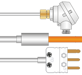 Our most popular style of Resistance Thermometer and ideal for most applications. Vast choice of terminations e.g. pot seals, cables, connectors, heads etc.
Rigid Stem
Our most popular style of Resistance Thermometer and ideal for most applications. Vast choice of terminations e.g. pot seals, cables, connectors, heads etc.
Rigid StemRTD Sensors
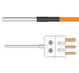 Ideal for rigid stem applications or where the sensor is shorter than 50mm, limited to 250°C. Wide choice of terminations
Hand Held
Ideal for rigid stem applications or where the sensor is shorter than 50mm, limited to 250°C. Wide choice of terminations
Hand HeldRTD Sensors
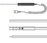 A range of hand held Resistance Thermometers to suit a variety of applications from general purpose to surface and air temperature measurements
RTD Sensors for
A range of hand held Resistance Thermometers to suit a variety of applications from general purpose to surface and air temperature measurements
RTD Sensors forSurface Measurements
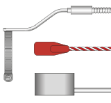 A wide range of Resistance Thermometers for surface measurements including self adhesive patch, pipe, magnetic etc.
RTD Theory
The resistance that an electrical conductor exhibits to the flow of an electric current is related to its temperature, essentially because of electron scattering effects and atomic lattice vibrations. The basis of this theory is that free electrons travel through the metal as plane waves modified by a function having the periodicity of the crystal lattice. The only little snag here is that impurities and what are termed lattice defects can also result in scattering, giving resistance variations. Fortunately, this effect is largely temperature-independent, so does not pose too much of a problem.
In fact, the concept of detecting temperature using resistance is considerably easier to work with in practice than is thermocouple thermometry. Firstly, the measurement is absolute, so no reference junction or cold junction compensation is required. Secondly, straightforward copper wires can be used between the sensor and your instrumentation since there are no special requirements in this respect.
The first recorded proposal to use the temperature dependence of resistance for sensing was made in the 1860’s by Sir William Siemens, and thermometers based on the effect were manufactured for a while from about 1870. However, although he used platinum (the most widely used material in RTD thermometry today), the interpolation formulae derived were inadequate. Also, instability was a problem due mainly to his construction methods - harnessing a refractory former inside an iron tube, resulting in differential expansion and platinum strain and contamination problems. Callendar took up the reins in 1887, but it was not until 1899 that the difficulties were ironed out and the use of platinum resistance thermometers was established.
It is now accepted that as long as the temperature relationship with resistance is predictable, smooth and stable, the phenomenon can indeed be used for temperature measurement. But for this to be true, the resistance effects due to impurities must be small - as is the case with some of the pure metals whose resistance is almost entirely dependent on temperature. However, since in thermometry almost entirely is not good enough, the impurity-related resistance must also be (for all practical purposes) constant such that it can be ignored. This means that physical and chemical composition must be kept constant. An important requirement for accurate resistance thermometry is that the sensing element must be pure. It must also be (and remain) in an annealed condition, via suitable heat treatment of the materials such that it is not inclined to change physically. Then again, it must be kept in an environment protected from contamination so that chemical changes are indeed obviated.
Meanwhile, another challenge for the manufacturer is to support the fine, pure wire adequately, while imposing minimum strains due to differential expansion between the wire and its surroundings or former - even though the sensors may be attached to operating plant, with all the rigours of this characteristically arduous environment. Depending upon the accuracy you are after, the relationship governing platinum resistance thermometer output against temperature follows the quadratic equation:
Rt /R0 = 1 + At + Bt2
(above 0°C this second order approach is more than adequate)
or Rt /R0 = 1 + At + Bt2 + Ct3 (t-100)
(below 0°C, if you are looking for higher accuracy of representation, the third order provides it).
Therefore:
t = (1/α)(Rt - R0)/R0 + δ(t/100)(t/100 -1)
Where: Rt is the thermometer resistance at temperature t; R0 is the thermometer resistance at 0°C; and t is the temperature in °C. A, B and C are constants (coefficients) determined by calibration. In the IEC 60751 industrial RTD standard, A is 3.90802 x 10⁻³; B is -5.802 x 10⁻⁷; and C is -4.2735 x 10⁻¹². Incidentally, since even this three term representation is imperfect, the ITS-90 scale introduces a further reference function with a set of deviation equations for use over the full practical temperature range above 0°C (a 20 term polynomial). The a coefficient, (R100 - R0)/100 . R0, essentially defines purity and state of anneal of the platinum, and is basically the mean temperature coefficient of resistance between 0 and 100°C (the mean slope of the resistance vs temperature curve in that region). Meanwhile, δ is the coefficient describing the departure from linearity in the same range. It depends upon the thermal expansion and the density of states curve near the Fermi energy. In fact, both quantities depend upon the purity of the platinum wire. For high purity platinum in a fully annealed state the a coefficient is between 3.925x10⁻³/°C and 3.928x10⁻³/°C.
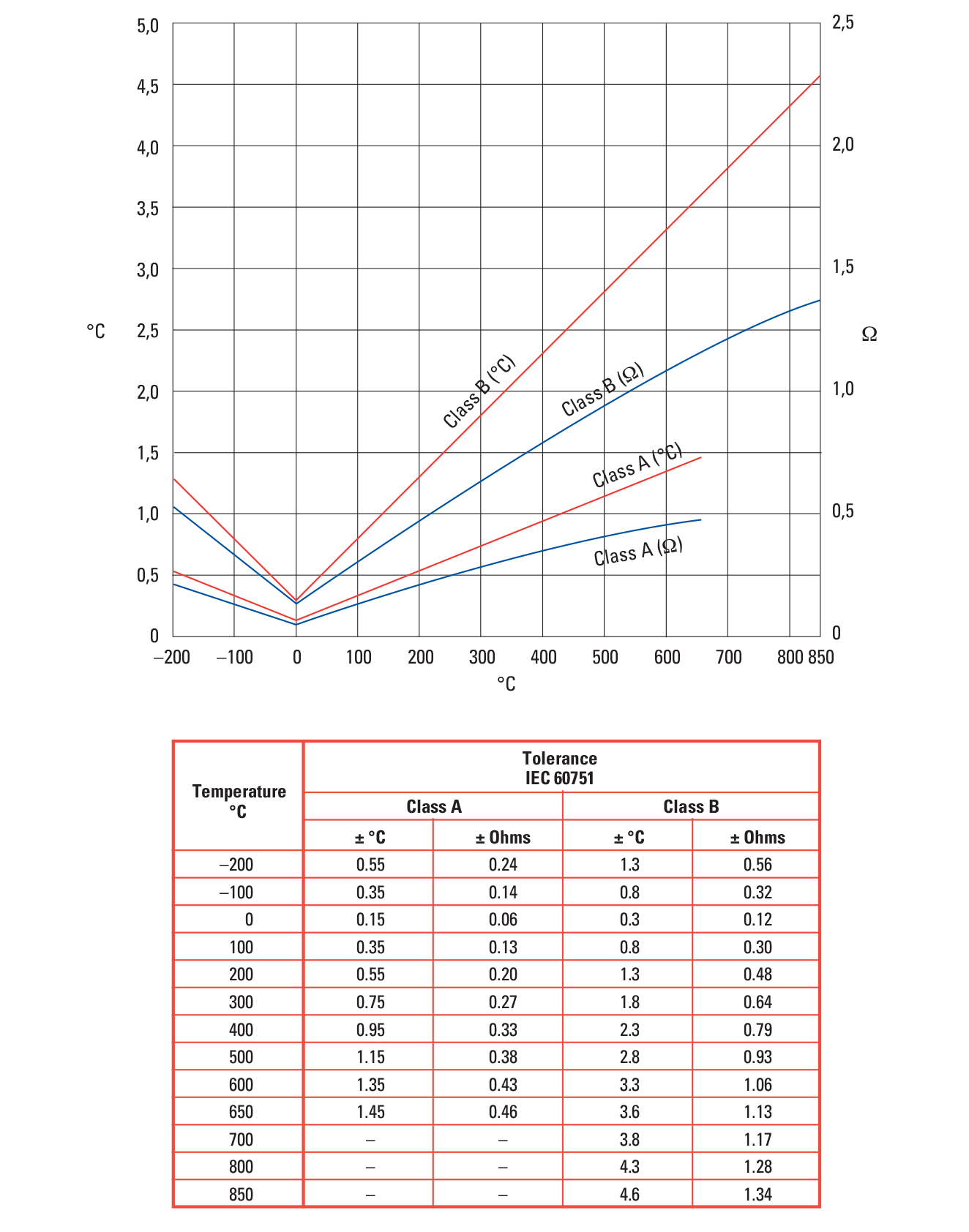
For commercially produced platinum resistance thermometers, standard tables of resistance versus temperature have been produced based on an R value of 100 ohms at 0°C and a fundamental interval (R100 - R0) of 38.5 ohms (α coefficient of 3.85x10⁻³/°C) using pure platinum doped with another metal (see Part 2, Section 6). The tables are available in IEC 60751, tolerance classes A and B.
Resistance Thermometer Materials
Several materials are available to fulfil the basic requirements of providing a predictable, smooth and stable temperature with resistance relationship. They include copper, gold, nickel, platinum and silver. Of these, copper, gold and silver have inherently low electrical resistivity values, making them less suitable for resistance thermometry - although copper does exhibit an almost linear resistance relationship against temperature.
In fact, because of this and its low price, copper is used in some applications, with the caveat that above moderate temperatures it is prone to oxidation and is generally not all that stable or repeatable. This notwithstanding, it can come into its own in applications where average temperatures over a long stem length are required, especially within the range -100°C to +180°C.
Nickel and nickel alloys are also relatively low cost and have high resistivities and high resistance versus temperature coefficients, making them very sensitive. However, they suffer from being non-linear with temperature and sensitive to strain. They also exhibit an unfortunate inflexion around the Curie point (358°C) which makes the derivation of the resistance to temperature expressions rather more complicated. These materials are therefore restricted to the temperature range of about -100°C to +180°C.
This leaves platinum, which has considerable advantages that make it well suited to resistance thermometry. Firstly, being a noble metal, it has a wide and unreactive temperature range. Secondly, its resistivity is more than six times that of copper. Thirdly, it has a reasonable, simple and well understood, although not entirely linear, resistance vs temperature relationship. Finally it can be obtained in a very pure form, and drawn into fine wires or strips very reproducibly, making the production of interchangeable detectors relatively easy.
Although platinum is not cheap, only very small amounts are needed for resistance thermometer construction its expense is therefore not a significant factor in calculating the overall cost. On the down side, it is contaminated by a number of materials, particularly when heated, so support and sheath materials have to be chosen carefully. Furthermore, heat treatment of the material is particularly important in view of the presence of vacancy defects which are present at all temperatures unless annealed out.
Beyond these materials, molybdenum film resistors are available, with useful, stable ranges around the -50 to +200°C mark. Semiconductor materials, like thermistors made from various metal oxides, are also available, which with the advent of better manufacturing methods and improved linearisers, can cover a very wide temperature range. However, no standardisation of these devices has been achieved, and they are beyond the scope of this guide. Meanwhile, there is a place for germanium RTD’s below 100K, and especially 10K where the resistivity of platinum is too small for practical purposes. However, the resistance/temperature relationship is not exactly trivial and neither is calibration. Then we get into the realms of carbon-glass RTD’s which exhibit negative temperature coefficients and high sensitivity at very low temperatures. Beyond this, there is the rhodium-iron alloy for temperatures right down to 0.5K.
RTD Elements
As covered above, to achieve high stability, platinum sensor elements must be (and remain) in a fully annealed condition and contamination free. Support and sheath materials and construction must be carefully selected and clean to avoid sensor poisoning and strain.
While below 250°C contamination is rarely a problem, above this temperature, materials of construction, insulation and so on (particularly base metals, some forms of mica and borosilicate glass) can react with, or dissolve in the Platinum. So, special mounting methods are required. RTD’s that are hermetically sealed also need some oxygen in the filling gas to keep the problem elements oxidised and thus relatively harmless to the sensor. As for purity of the platinum, in industrial RTD’s lower a coefficient purity platinum wire is used (see Part 1, Section 4), than in primary standard and laboratory style thermometers because the application warrants a physically more robust element and one that is more forgiving of its surroundings in terms of contamination. So pure platinum wire doped with another metal is used to get to the standard specifications of the IEC and British standards for temperature vs resistance definition, and tolerance limits up and down the temperature scale. Other general points include the need to construct the sensors such that thermoelectric voltages, generated through the use of dissimilar metals (as per thermocouples), cancel one another out. Also, the insulation resistance between the RTD itself (including its internal connection wires) and the protective sheath (if any) must be adequate (as per IEC 60751 - see Part 1, Section 4.3). Beyond this, the coil windings need to be non-inductive, current flow must not elicit significant self-heating (see Part 1, Section 4.2) and DC and AC (up to 500 Hz) must be provided for. Also, it is important to ensure that a negligible amount of heat will be conducted along the sheath, internal wires and insulators.
Before we go on to describe some of the sensor styles, it is just worth pointing out that the assemblies detailed can also be used with metals other than platinum, see Part 1, Section 4.2. A wide range of shapes and sizes is available, the only major restrictions being wire support, contamination resistance and an adequate electrical resistance with appropriate insulation. For example, surface areas can be made large in proportion to the volume occupied to encourage fast response. Alternatively, the RTD can be made very small to allow for point temperature sensing or the sensor could be made long, or large, to facilitate temperature averaging over whatever length, or area, is required.
RTD Element Styles
Various construction methods have been used in the development of RTD’s. They include: Callendar’s original, with its mica cross around which the platinum wire was wound (problems included dehydration and embrittlement of the mica for exposed sensors, and condensation in gas filled and sealed versions), porcelain cross varieties with coiled wire (heavy and introducing time lag difficulties), twisted silica strip units forming a helical support for the coil, machined ceramic formers with grooves for the coil and so on.
For laboratory standard instruments, the element may be a thin wire (typically 0.07mm) wound in a helical form and supported by frictional contact in a closely fitting thin walled glass, silica or alumina tube. This may be U shaped, or two separate tubes twisted together for mutual support, with platinum coils in each, connected at the bottom by a thick platinum wire sealed into the glass and welded to the coils. Four platinum connection leads are sealed into the top (two in each limb) and the whole assembly may be provided with a silica outer sheath (see Figure 6.1). All designs are aimed at producing a strain-free thermometer which can expand and contract on heating and cooling without the wire rubbing or being scratched by its support.
For high precision thermometry above -189°C, the resistance element is cleaned and mounted in the glass or silica tube with the leads passing through a glass seal at the top. The device is then evacuated and back filled with dry air or high purity argon with a few percent of oxygen - to ensure that the platinum operates under oxidising rather than reducing conditions, such that remaining contaminants are preferentially oxidised during operation. Also, to maximise resistance between leads at higher temperatures, the leads are insulated from one another using mica, silica or sapphire.
Meanwhile, for very low temperature purposes, capsule type designs are favoured (see Figure 6.2). Here, a thin walled platinum tube, about 50mm long by 5mm OD with a glass head, contains the resistance coil wound on a former. After evacuation, this type of device is filled with helium, for good thermal contact, before sealing.
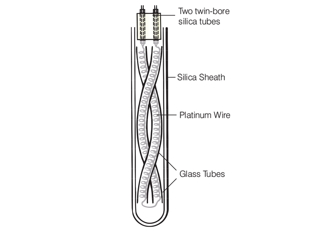
Figure 6.1: Traditional laboratory style RTD sensor

Figure 6.2: Capsule design platinum RTD
With all these devices, resistance at 0°C is usually 25 ohms, the a value is around 0.003926/°C and sensitivity is around 0.1 ohm/°C. However, for elevated temperature work, RTD resistance is reduced (to between 0.2 and 5 ohms at 0°C) to minimise shunting effects caused by insulation leakage at high temperatures. There are several designs for this kind of work, one being the National Bureau of Standards’ (USA) bird cage device (see Figure 6.3). This has eight parallel platinum lengths threaded through silica discs and connected in series, giving a resistance at 0°C of just 0.2 ohms, moving up to 1 ohm at 1,000°C. However, there are many designs: silica crosses with notches for bifilar helical coil winding (and other winding styles), silica rods with helical wiring grooves, silica strips, again grooved and so on.

Figure 6.3: Bird cage high temperature RTD
Industrial RTD Designs
Realistically it is not possible to achieve laboratory standard precision using these devices in industry, as price, fragility and poor vibration resistance will not permit. So the more general purpose, industrial type sensors are built to withstand conditions on plants. Modern pure ceramic materials, along with techniques for winding the wires into their ceramic support assemblies, combined with special annealing processes and advanced vibration resistance, means that high stability designs have made a substantial impact.
Firstly, the lower a coefficient metal doped platinum wire tends to be used (in accordance with the IEC standard, as mentioned above). Fine wire is drawn through laser drilled sapphire or diamond dies giving fully repeatable results without contamination. Then, manufacturers aim to provide as full support as possible for the wires, to enable best vibration and shock resistance, while also allowing the wires to be reasonably free to expand and contract without strain - thus also ensuring stability (a compromise situation).
A common style involves wires wound on glass or ceramic bobbin formers that have similar temperature versus expansion characteristics to that of the platinum wire. The windings are then secured and sealed with a coating of ceramic cement or glass (see Figure 6.4), selected to match the expansion rate of the platinum.
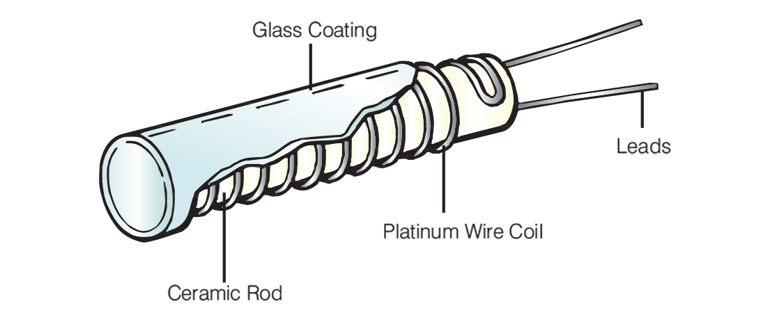
Figure 6.4: Classic cylindrical style industrial wire wound RTD
Although tough and more than adequate for most requirements, these devices do exhibit poorer stability during temperature cycling, smaller operational temperature range (up to about 500°C) and greater hysteresis than RTD’s with partially supported coils. Another arrangement involves wire coils set in grooves (see Figure 6.5).
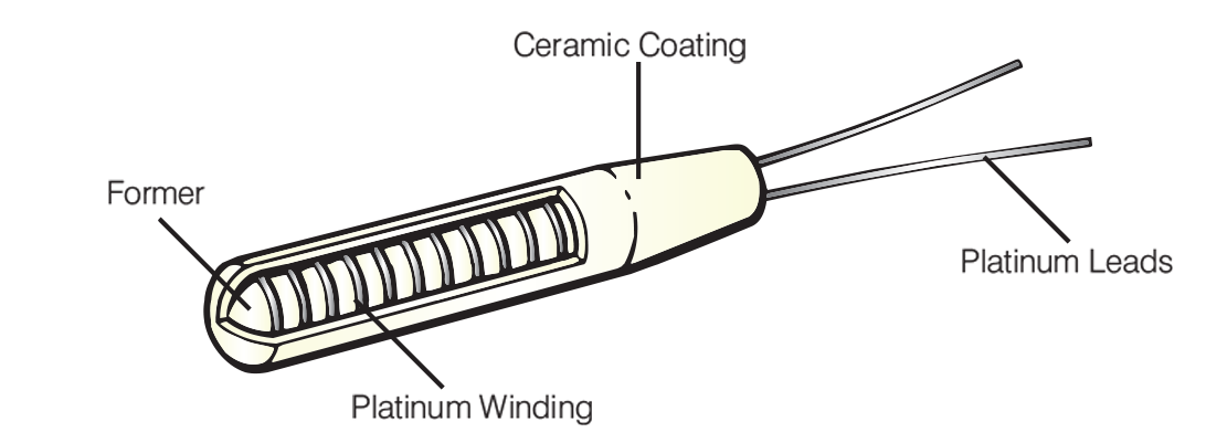
Figure 6.5: Cylindrical Sensor with Wire Coil set in Grooves
As an alternative, partially supported coil constructions offer more flexibility in the ruggedness versus stability trade-off. A common assembly comprises helical platinum coils mounted in holes in a multi-bore alumina tube, with the coil being anchored by small amounts of glass (providing partial rather than full support, see Figure 6.6) such that a large proportion of the coils are free to move. The wires are then attached to more robust leads. Then again, another approach relies on embedding the platinum coils in alumina powder to reduce vibration effects further.

Figure 6.6: Partial Support using Multi-bore Alumina Tubing
These assemblies, if properly engineered, are the closest to meeting the requirements of the working standard thermometer, offering either low vibration resistance and very high stability, or higher vibration resistance and slightly lower, but still excellent stability. With these kinds of industrial devices, stabilities of a few hundredths of a degree over the range -200 to +850°C can be provided. Further, they need not be hermetically sealed - so air can circulate around the platinum wire where the environment allows. Typically, the sensors are about 25mm long by about 3mm diameter and the resistance element will be trimmed at 0°C to precisely 100 ohms.
Film Thermometers
A more recent development for platinum resistance thermometer construction is that of depositing the platinum material as a film (thick or thin) pattern on a suitable substrate. With thin film devices, platinum is evaporated onto the substrate using vacuum semiconductor fabrication techniques, whereas with thick film sensors, a glass/platinum paste is essentially silk screen printed on to the substrate. Both approaches allow the 'element' to be bonded to a flat or cylindrical surface as appropriate to the application (see Figure 6.7).
Performance today can almost equal that obtained with the wire wound devices (certainly the more basic glass coated versions), particularly with thin film sensors over the range -50°C to 500°C. Benefits include: fast thermal response (due mainly to low mass and the intimate contact made with the substrate), insensitivity to vibration and lower cost than their wire wound counterparts.

Figure 6.7: Wire Wound and Thin film alternatives for RTD’s
There is, however, some debate about the inherent stability of these designs, particularly over extended ranges. Firstly, they are not as free to expand and contract as their wire wound, partially supported alternatives (although this criticism applies equally to the glass sealed wire wound units). Secondly, with the small quantity of platinum used, they are more subject to contamination, and sealing them with glass is not necessarily the ideal answer. Thirdly, film characteristics can vary from batch to batch, Still, as lower cost surface temperature and air temperature sensors offering medium to high precision - say ±0.05% stability over the temperature range - they have a very useful role to fulfil. It is just worth remembering that equivalent stability for wire wound partially supported devices would be an order of magnitude better at least - ±0.005% stability.
RTD Colour Codes
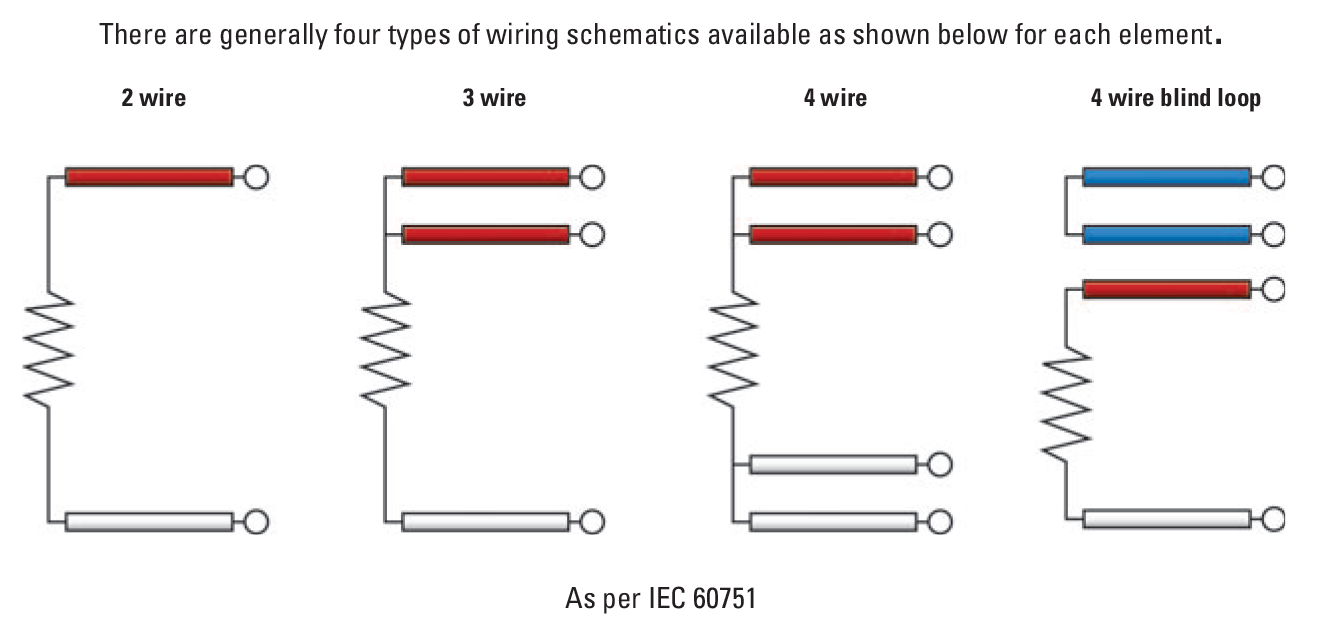
RTD Tolerances

 France
 Germany
 Spain
Spain Netherlands
 Italy
Italy Hungary
 United States
 Australia
