What is a Themocouple? How do Thermocouples work?
What is a Thermocouple?
A thermocouple is a type of temperature sensor used for temperature measurement and control applications across a wide range of industries. There are many types of thermocouple available each with different design features and constructions. Thermocouples cover a wide temperature range and are suitable for most industrial and scientific temperature measurement applications.
Thermocouples consist of two different metal wires joined at one end to form a junction. When this junction is heated or cooled, it creates a temperature gradient between the junction and the ends of the wires. This produces a small voltage, called a thermoelectric voltage, which is proportional to the temperature difference between the two ends.
Thermoelectric voltage was first discovered by TJ Seebeck in the early 19th century and is known as The Seebeck Effect. In theory, any two dissimilar wires can be used but in practice, only a few conductor material combinations generate a voltage that is predictable, stable and usable and these combinations are designated as 'thermocouple types', such as Type K, Type J, Type T etc., with each type suitable for a specific temperature range and environment.
Thermocouples then, are used for reliable and accurate temperature measurements in a wide range of industries from manufacturing processes and automotive applications to aerospace and healthcare. Their durability, simplicity, and wide temperature range make them a good choice for temperature monitoring in most conditions and environments.
We specialise in the manufacture of thermocouples designed to meet your specific application needs. From surface thermocouples or robust mineral insulated probes to high temperature ceramic sheathed sensors, our engineers are available on 01895 252222 or via the Live Chat to assist you with design advice.
Need advice on choosing a thermocouple?
Contact one of our experienced engineers on
01895 252222 or use the Live Chat button.
Popular Thermocouples
Mineral Insulated Thermocouples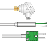 Rugged sensors, ideal for most applications. Vast choice of terminations e.g. pot seals, cables, connectors, heads etc.
General Purpose Thermocouples
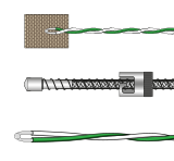 A wide range of thermocouples to suit many applications. Hand held, surface, bayonet, bolt, patch styles etc.
Thermocouples for Surface Measurements
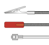 A range of thermocouples to suit various surface temperature measurement applications.
Miniature Thermocouples
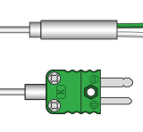 Ideal for precision temperature measurements where minimal displacement and a fast response is required.
Do I need a thermocouple or an RTD?
Please see our useful guide on whether to use a thermocouple or rtd for your application.

How does a Thermocouple work?
If there is a temperature gradient in an electrical conductor, the energy (heat) flow is associated with an electron flow along the conductor and an electromotive force (EMF) is then generated in that region. Both the size and direction of the EMF are dependent on the size and direction of the temperature gradient itself as well as on the material forming the conductor. The voltage is a function of the temperature difference along the conductor length. This effect was discovered by TJ Seebeck in 1822.
The voltage appearing across the ends of the conductor is the sum of all the EMFs generated along it. For a given overall temperature difference, T1-T2, the gradient distributions shown in figures 2.1 a, b and c produce the same total voltage, E. As long as the conductor has uniform thermoelectric characteristics throughout its length.
The output voltage of a single conductor as shown, is not however normally measurable since the sum of the internal EMFs around a completed circuit in any temperature situation is zero. So, in a practical thermocouple sensor, the trick is to join two materials having different thermoelectric EMF/temperature characteristics in order to produce a usable net electron flow and a detectable net output voltage.
Thus, two connected dissimilar conductors, A and B, exposed to the same temperature gradients given in figure 2.1 generate outputs as shown in figure 2.2. Basically, there is a net electron flow across the junction caused by the different thermoelectric EMFs, in turn resulting from the interaction of the gradient with the two different conductors. Hence the term, 'thermocouple'.
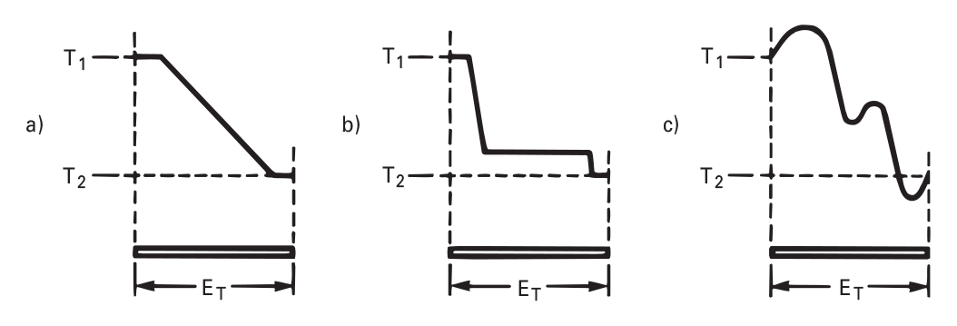
Figures 2.1 a,b,c: Temperature Distributions Resulting in Same Thermoelectric EMF

Figures 2.2 a,b,c: Thermocouple EMFs Generated by Temperature Gradients
It is worth noting that the thermoelectric EMF is generated in the region of the temperature gradient and not at the junction as such. This is an important point to understand since there are practical implications for thermocouple thermometry. These include ensuring that thermocouple conductors are physically and chemically homogenous if they are in a temperature gradient. Equally, the junctions themselves must be in isothermal areas. If either of these conditions is not satisfied, additional, unwanted EMFs will result.
Incidentally, any number of conductors can be added into a thermoelectric circuit without affecting the output, so long as both ends are at the same temperature and that homogeneity is ensured. This leads to the concept of extension leads and compensating cables, enabling probe conductor lengths to be increased. See Part 2, Section 3.
Returning to figure 2.2, in fact the output, ET, is the same for any temperature gradient distribution over the temperature difference T1 and T2, provided that the conductors again exhibit uniform thermoelectric characteristics throughout their lengths. Since the junctions M, R1 and R2 represent the limits of the EMF-generating conductors, and since the remaining conductors linking the measuring device are uniform copper wire, the output of the thermocouple is effectively a function only of the two main junctions’ temperatures. In essence this is the basis of practical thermocouple thermometry.
The relevant junctions are the so-called measuring junction (M) and the junction of the dissimilar wires to the copper output connections (usually, a pair of junctions), called the reference junction (R), as in Figure 2.2. So long as the reference junction (R) is maintained at a constant, known temperature, the temperature of the measuring junction (M) can be deduced from the thermocouple output voltage. Thermocouples can thus be considered as differential temperature measuring devices - not absolute temperature sensors.
There are important points to note at this stage. Firstly, thermocouples only generate an output in the regions where the temperature gradients exist, not beyond. Secondly, accuracy and stability can only be assured if the thermoelectric characteristics of the thermocouple conductors are uniform throughout. Finally, only a circuit comprising dissimilar materials in a temperature gradient generates an output.
Cold Junction Compensation
There are calibration tables (emf tables) for each thermocouple type, ralting output voltage to the temperature of the measuring junction. Throughout thermocouple thermometry it is clearly necessary to refer sensor voltage output to these in some way to ascertain true temperature
Most importantly, different net voltage outputs are produced for a given temperature difference between the measuring and reference junctions if the reference junction temperature itself is allowed to vary. So, the calibration tables mentioned above always expressly assume that the reference junction is held at 0°C.
This can be achieved by inserting the copper junction(s) into melting ice, via insulating glass tubes, or into a temperature controlled chamber, like an isothermal block with suitable temperature sensors. For industrial measurement today, this kind of function is normally performed by temperature correcting electronics - while linearising electronics (usually digital), harnessing curve fitting techniques, look after the inherent non-linearities as per the calibration tables (more in Part 1, Section 5).
Essentially, reference temperature variations are sensed by a device such as a thermistor as close as possible to the reference junction. An EMF is then induced which varies with temperature so as to compensate for temperature movements at the reference terminals.
Cold Junction Compensation Methods
As explained earlier, thermocouples provide an output which is related to the temperatures of the two junctions. For them to function as absolute temperature measuring devices, rather than differential, the reference junctions must be maintained at a known temperature (see Figure 5.1).
An established, simple method of maintaining reference temperature stability, still used in laboratories today, is to immerse the reference junctions in a slush of melting ice. Given that you have pure water ice, the temperature plateau during the melting process is established at a constant 0°C within ±0.001°C. In practice, all that is required is an ice-filled Dewar flask and the set-up is then potentially quite accurate. However, it does require regular attention and replenishment for anything other than short term use and is clearly inappropriate for industrial requirements. Sources of error include the 4°C reference offset which will occur if enough ice melts so that the reference junctions are actually immersed only in water - with the ice floating above! Also if the ice used has been stored in a freezer, it will be a lot colder than 0°C.
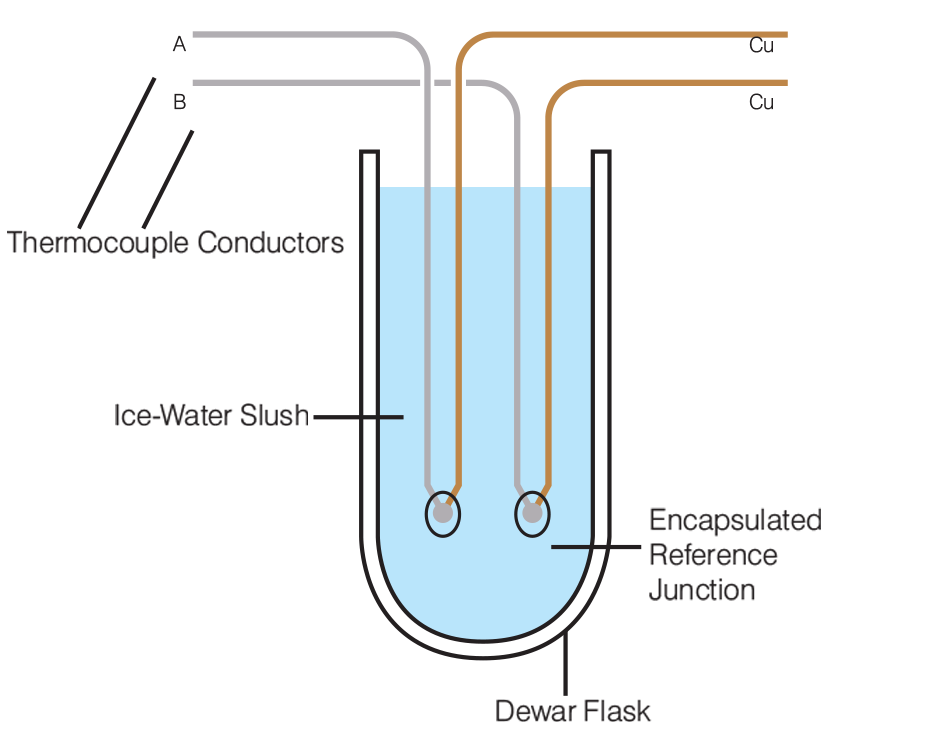
Figures 5.1: Dewar flask with Reference Junctions
Not surprisingly, there are more practical alternatives for industrial use, also designed to provide a reference temperature of 0°C. One involves an automatic temperature-controlled enclosure, into which the reference junctions are inserted. This holds the junctions continuously at the ice point, using semiconductor thermoelectric cooling (Peltier) devices. Here temperature errors are typically less than 0.1°C. The use of an ice point reference, or its equivalent (however generated), is still preferable to the alternatives, not only on the grounds of accuracy and stability, but also because the reference tables for thermocouples are based on a 0°C reference temperature.
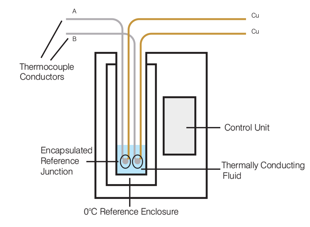
Figures 5.2: Temperature controlled enclosure
Another very common device today is based on a temperature sensitive electrical network (there are several options) which tracks the reference junction temperature and develops an equivalent voltage. Such so-called cold junction compensation is incorporated into each thermocouple circuit, or the measuring instrument itself at the point of connection (see below). These devices are available as discrete modules, mains or battery powered and provide for accuracy within a few °C.
Many of the instruments designed to operate with thermocouples provide terminals for direct connection to the thermocouple or extension cable conductors without any need for a separate reference junction as such. Such devices as electronic thermometers, temperature controllers, data loggers, etc, frequently incorporate their own equivalent ice point reference voltage generators (as described above).
The temperature at the connection point might be determined by an integral resistance thermometer (see Part 2, Section 6), thermistor or transistor, and thus a suitable reference voltage developed. Incidentally, it is worth taking care over the physical siting of the reference generator, since accuracy and stability of the thermocouple reading are dependent on the network involved actually being in the same temperature environment as the connections themselves.
In any event, the reference voltage can be added to the thermocouple output either by inclusion in the electrical circuit, or, particularly in the case of controllers, data loggers and other digital systems, by data manipulation in the temperature calculations. In fact, many modern controllers, loggers, etc can accommodate the latter approach.
For large schemes involving many thermocouples, racking systems and cabinets are also available having, say, 100 equivalent reference junctions already fitted into a uniform temperature enclosure. The enclosure might be an ice point unit as already described, or it might equally be a thermally stable metal block which maintains a reasonably steady temperature close to that of its surroundings. In the latter case, the temperature of the block is continuously monitored by an electrical compensator, and again, the equivalent ice point voltage is then available to be added to each thermocouple signal output - electrically, or numerically.
Beyond these, there are also reference units designed for enclosures operating at elevated temperatures. These can be useful in areas with particularly high ambient temperatures, but the thermocouple outputs will have to be adjusted to the equivalent 0°C values. In essence, as long as the reference temperature is known, the temperature of the measuring junction can be derived by adding in a correction factor from standard tables covering the thermocouple concerned.
See our dedicated thermocouple Cold Junction Compensation page
Material Types
Most conducting materials can produce a thermoelectric output. However, when considerations like width of the temperature range, actual useful signal output, linearity and repeatability (the unambiguous relationship of output to temperature), are taken into account, there is a somewhat restricted sensible choice. Material selections have been the subject of considerable work over several decades, on the part of suppliers, the main calibration and qualifying laboratories and academia. So, the range of temperatures covered by usable metals and alloys, in both wire and complete sensor form, now extends from -270°C to 2,600°C.
Naturally, the full range cannot be covered by just one thermocouple junction combination. There are internationally recognised type designations, each claiming some special virtue. The British standard BS EN 60584-1 (formerly BS 4937) and the International standard IEC 60584 refer to the standardised thermocouples (these are described by letter designation - the system originally proposed by the Instrument Society of America (see Part 1, Section 3).
In general, these are divided into two main categories: rare metal types (typically, platinum vs platinum rhodium) and base metal types (such as nickel chromium vs nickel aluminium and iron vs copper nickel (Constantan)). Platinum-based thermocouples tend to be the most stable, but they’re also the most expensive. They have a useful temperature range from ambient to around 2,000°C, and short term, much greater (-270°C to 3,000°C). The range for the base metal types is more restricted, typically from 0 to 1,200°C, although again wider for non-continuous exposure. However, signal outputs for rare metal types are small compared with those from base metal types.
Another issue here is the inherent thermoelectric instability of the base metal thermocouple, Type K, with both time and temperature (although Types E, J and T have also come in for some criticism see Part 1, Section 3). Hence the interest in Type N thermocouples (Nicrosil vs Nisil), with the best of the rare metal characteristics at base metal prices, with base metal signal levels and a slightly extended base metal temperature range.

 France
 Germany
 Spain
Spain Netherlands
 Italy
Italy Hungary
 United States
 Australia
